Latest Electronic And Communication (EC) Engineering Mini Project
Published on 14 April , 2019

1 :- Automated Railway Crossing Project:
This particular electronics project is actually a solution to a real-life problem statement. We have been hearing lot of news lately regarding the number of people losing lives, vehicles getting into accident at the unmanned railway gates. This electronics project gives an kefficient solution to this, through which the railway gates can be programmed to open and close automatically by sensing the arrival of train. As it is addressing a serious problem that we are facing, being an electronics engineer you should do this project to understand the technology behind it.
This EC project works by 2 simple mechanisms. First an IR sensor is used to detect the arrival and departure of the train at certain location from the railway gate and will send the data collected (as signals) to the micro-controller. Then a micro-controller is used to detect these signals and facilitates the operation of motors which will then open/ close the gate. You can use IR sensors for detecting the train movement, micro-controller like 8051, 8052, Arduino Uno to act as the brain of the system and D.C motors to operate the railway gates.
2 :- Robotic Arm Project :
Robotics is being widely adapted in the industries of today to increase their operational efficiency. Robotic arm is one such mechatronics application that can operate autonomously to handle the industrial process that needs more physical effort/ contagious in nature. By doing this electronics project you will build a Robotic Arm that can be controlled by human hand gestures to carry out actions like pick/ place.
You Need To Work With Following Components :-
- ADXL Accelerometer Sensor –- It will be used to detect the human gestures (3 axis)
- Arduino Uno - Acts as the brain and process the signals coming from the ADXL sensor
- Servo Motors – Multiple of them will be used to facilitate individual arm movements
Note :- Watch This Video With Full Explain And Practical In This Video :-
http://youtu.be/1rz1gQDspz0
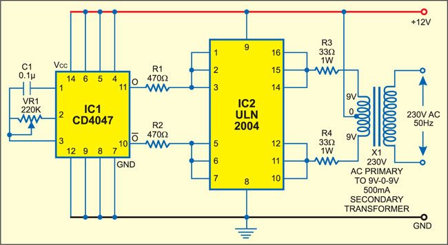
3 :- Low Power Inverter Circuit
IC CD4047 (IC1) is a monostable. It is wired in astable mode and produces symmetrical pulses of 50 to 400 Hz, which are given to IC2 via resistors R1 and R2.

IC ULN2004 (IC2) is a popular 7-channel Darlington array IC. Here, the three Darlington stages are paralleled to amplify the frequencies received from IC1. The output of IC2 is fed to transformer X1 via resistors R3 and R4.
Transformer X1 (9V-0-9V, 500mA secondary) is an ordinary step-down transformer that is used here for the reverse function, i.e., step up. That means it produces a high voltage. Resistors R3 and R4 are used to limit the output current from the ULN to safe values. The 230-250V AC output is available across the high-impedance winding of the transformer’s primary windings.
Website Create Student Name :-
Gowsami Umangbharathi B.
Keshavala Jayesh K.
Koladiya Bhavyesh R.
Gowsami Umangbharathi B.
Keshavala Jayesh K.
Koladiya Bhavyesh R.

